Setting up your Arduino/Genuino Mega
The Arduino/Genuino Mega is a mid-level product in a family of easy-to-use microcontroller boards which connect to a computer via a USB port and allow you to control all manner of devices.
It can be programmed directly using the Arduino IDE software, but if you are new to computer control and programming, the MECControl system gives you a simpler way to get started.
When using an Arduino/Genuino Mega with MECControl, make sure that you place the following Board command somewhere in your sequence, otherwise MECControl will assume that you are using an Arduino/Genuino Uno:
Board Arduino/Genuino Mega
Inputs and outputs
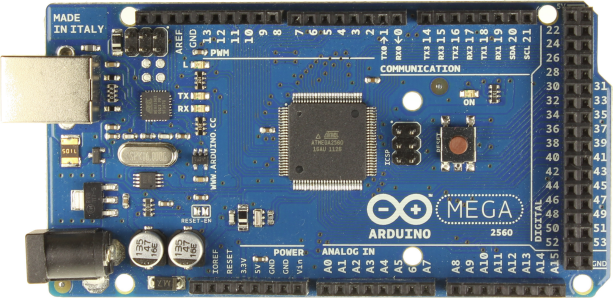
Here is a photo of the Arduino/Genuino Mega:

Along the top and the right-hand side are 54 connectors called pins, labelled 0 to 53 (with the exception of pins 23, 25, 27 and 29). These can be used as either digital inputs or digital outputs.
As outputs, they can be connected to devices such as LEDs, Motors and Meccanoid Servo Motors.
As inputs, they can be connected to devices such as Buttons and Switches.
Along the bottom are 16 pins labelled A0 to A15. These are analogue inputs which can be connected to devices such as Potentiometers, Buttons and Switches.
Powering the Arduino/Genuino Mega
The simplest way to power your Arduino/Genuino Mega is to plug it into your computer’s USB port. Your computer then provides it with a 5V DC supply of up to 500mA. This is sufficient to power the Arduino/Genuino Mega along with a few other low-current devices like LEDs, but if your Arduino/Genuino Mega will be controlling high-current devices such as Motors, you will probably need to power these from a separate regulated power supply.
Universal laptop computer power supplies can generally provide 4A at 12V DC, enough to run several 12V Motors.
Some USB mobile phone chargers provide 2A at 5V DC, ideal for devices such as Meccanoid Servo Motors.
Whatever power supply you choose, make sure that its negative lead is connected one of the ground pins labelled GND on your Arduino/Genuino Mega.
However, if your power supply’s voltage is higher than 5V, keep the positive lead away from your Arduino/Genuino Mega at all costs — it is strictly for use by the devices that your Arduino/Genuino Mega is controlling. Connecting it to one of the pins on your Arduino/Genuino Mega is likely to cause damage.
Experimenting
The best way to experiment with the Arduino/Genuino Mega and electronic components in general is to use a breadboard. A breadboard allows you to quickly connect components and wires to each other without soldering.
Many breadboards have lugs that allow multiple boards to be placed side-by-side and edge plates to be fitted for securing larger components such as buttons and switches.
Here is a photo of a typical breadboard, with superimposed lines showing how its pinholes are connected internally:

By convention and for convenience, one of the bottom rows of pins is normally connected to a ground pin, labelled GND, on your Arduino/Genuino Mega, and/or the negative lead from your power supply.
One of the top rows of pins is normally connected to a pin labelled 5V on your Arduino/Genuino Mega, or the positive lead from your power supply (but not both — see ‘Powering the Arduino/Genuino Mega’ above).
The pins in the central columns can then be used for connecting components and wires to each other.
It is easiest to use stiff single-core wire with breadboard (or ready-made jumper wires) and to stick to a colour code, such as the following:
- Use red wire for 5V from the Arduino/Genuino Mega or a power supply.
- Use black wire for ground from the Arduino/Genuino Mega and/or a power supply.
- Use yellow wire for 12V from a power supply.