Stepper Motors
Unlike normal motors, stepper motors contain multiple coils, allowing the position of the rotor to be precisely controlled by switching its four phases on and off in a particular stepping sequence.
Stepper motors cannot be directly connected to your Arduino/Genuino Uno or Mega for several reasons:
- They generally require a higher voltage and current than the Arduino/Genuino Uno or Mega can supply.
- The counter-electromotive force produced in their coils would damage the Arduino/Genuino Uno or Mega.
A circuit called an H bridge can be used to solve all of these problems.
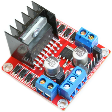
One of the most popular H bridge circuits is based on the L298 integrated circuit. It contains two identical H bridges, allowing you to control one stepper motor consuming up to 2A per coil at a voltage from 7.5V to 46V DC.
While you could build your own L298 H bridge circuit, it is cheaper and easier to buy a ready-built module. The examples below assume the use of such a module running from a 12V DC power supply, along with a 12V stepper motor.
Connecting stepper motors
The number of leads that a stepper motor has will tell you if it is a unipolar or bipolar motor (or can be either), and determine how it is connected to the L298 H bridge module.
You will need to check your motor’s datasheet or do some testing with a multimeter set to its resistance (Ω) range to determine which lead is which.
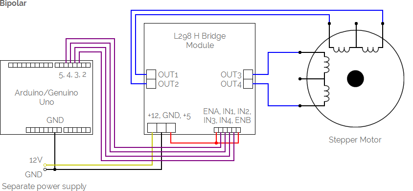
A motor with four leads
This bipolar motor has two leads for each of its two coils.
If you measure a low resistance between two of its leads, then these two leads are connected to the first coil, and the other two leads are connected to the second coil.
The motor can be connected to your Arduino/Genuino Uno or Mega and L298 H bridge module as shown in this example:
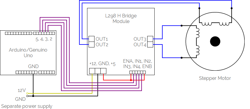
If the motor behaves erratically, swap the leads connected to one of the coils.
The inputs (IN1, IN2, IN3 and IN4) from the L298 H bridge module can be connected any of the digital pins on your Arduino/Genuino Uno or Mega, labelled 2-13 on the Uno and 2-53 on the Mega.
A motor with five leads
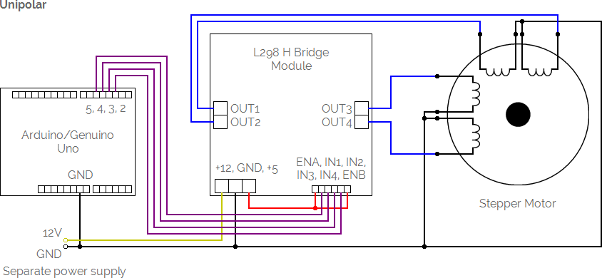
This unipolar motor has two leads for each of its two coils. A single lead is connected to the centre tap of both coils.
If you measure the same low resistance between one of its leads and all four of the others, then this lead is connected to the centre tap.
The motor can be connected to your Arduino/Genuino Uno or Mega and L298 H bridge module as shown in this example:
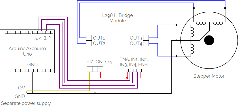
If the motor behaves erratically, swap the non-centre tap leads until the motor behaves correctly.
The inputs (IN1, IN2, IN3 and IN4) from the L298 H bridge module can be connected any of the digital pins on your Arduino/Genuino Uno or Mega, labelled 2-13 on the Uno and 2-53 on the Mega.
A motor with six leads
This motor has three leads for each of its two coils. Each coil has its own centre tap lead, so it can be used as a unipolar motor or as a bipolar motor.
If you measure the same low resistance between one of its leads and two of the others, then this lead is connected to the centre tap for the first coil, with the other two also being connected to the first coil. If you measure the same low resistance between one of the remaining three leads and the other two, then this lead is connected to the centre tap for the second coil, with the other two also being connected to the second coil.
The motor can be connected to your Arduino/Genuino Uno or Mega and L298 H bridge module as shown in these examples:
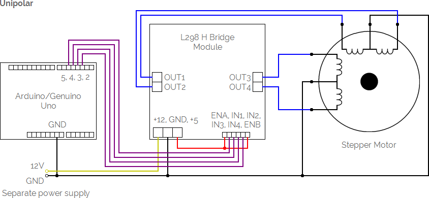
If the motor behaves erratically, swap the non-centre tap leads until the motor behaves correctly.
The inputs (IN1, IN2, IN3 and IN4) from the L298 H bridge module can be connected any of the digital pins on your Arduino/Genuino Uno or Mega, labelled 2-13 on the Uno and 2-53 on the Mega.
A motor with eight leads
This motor has two leads for each of its four coils. Leads from two adjacent coils can be joined to create a centre tap, so it can be used as a unipolar motor or as a bipolar motor. The coils can also be connected in parallel to obtain higher torque.
If you measure a low resistance between two of its leads, then these two leads are connected to the first coil. Measure the resistance between further pairs of leads to find out which leads are connected to the second, third and fourth coils.
The motor can be connected to your Arduino/Genuino Uno or Mega and L298 H bridge module as shown in these examples:
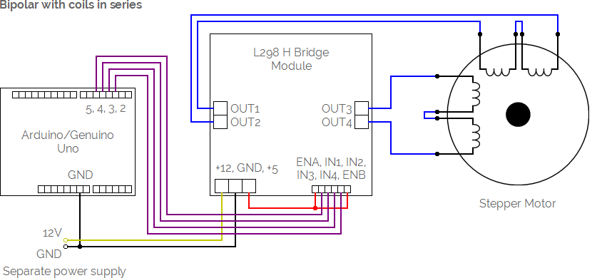
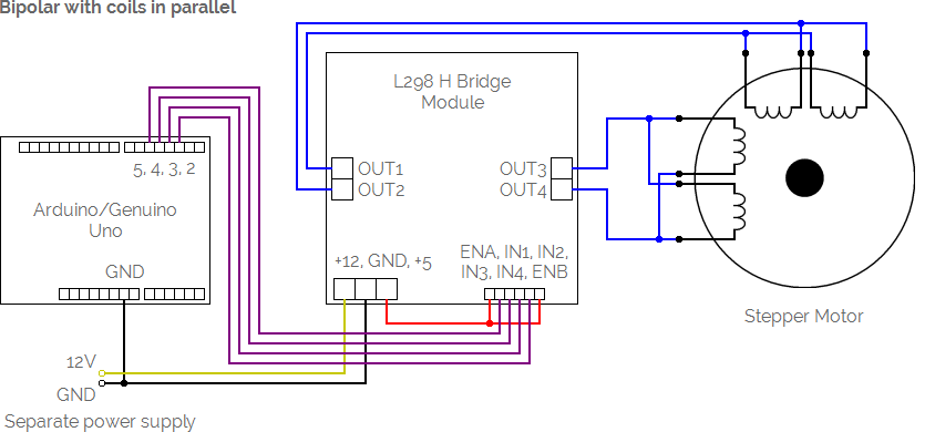
If the motor behaves erratically, swap the non-centre tap leads until the motor behaves correctly.
The inputs (IN1, IN2, IN3 and IN4) from the L298 H bridge module can be connected any of the digital pins on your Arduino/Genuino Uno or Mega, labelled 2-13 on the Uno and 2-53 on the Mega.
Moving stepper motors
Once your stepper motor is connected to your Arduino/Genuino Uno or Mega via an L298 H bridge module, use the Connect command to give it a name and tell MECControl which pins it is connected to:
Connect Hand StepperMotor To Pins 2, 3, 4, 5
In this example, a StepperMotor named Hand has been connected via the digital pins labelled 2, 3, 4 and 5. The pins do not need to be consecutive, though if they are they can also be specified as a range:
Connect Hand StepperMotor To Pins 2-5
You can then refer to the stepper motor by name in later commands, as in this example:
Move Hand Clockwise By 10 Steps
This command moves the Hand stepper motor Clockwise by 10 steps. You could just as easily move the stepper motor Counterclockwise:
Move Hand CounterClockwise By 10 Steps
You can also refer to an number stored in a previously defined variable:
Move Hand CounterClockwise By StepsToMove Steps
Sometimes it is useful to give the stepper motor actions names that mean something in the context of your project.
You can do this by adding named Actions to the end of the Connect command:
Connect Hand StepperMotor To Pins 2-5 Actions Left Right
Now these actions can be used with the Move command:
Move Hand Left By 10 Steps
MECControl will wait for the action to complete. This means other devices cannot be controlled while a stepper motor is moving, and any Button presses will be ignored.
Stepper motor speed
You can specify the speed of the stepper motor in steps per second:
Move Hand Clockwise By 200 Steps At 60 Steps Per Second
The speed can be anything from 0.1 to 1000 steps per second, in 0.1 increments.
You can also refer to a speed stored in a previously defined variable:
Move Hand Clockwise By 200 Steps At Speed Steps Per Second
Alternatively, you can move the motor over a given period of time:
Move Hand Clockwise By 200 Steps Over 60 Seconds
The time period can be anything from 0.1 to 60 seconds, in 0.1 second increments.
You can also refer to a time period stored in a previously defined variable:
Move Hand Clockwise By 200 Steps Over Time Seconds
Disabling stepper motors
A stepper motor normally holds itself at the position set by the last Move command.
To allow the stepper motor to move freely, you can use the Disable command:
Disable Hand