Relays
One way to control high-voltage or high-current devices from your Arduino/Genuino Uno or Mega while ensuring electrical isolation is to use a relay — an electro-mechanical switch activated by a coil.
Relays are available in a vast variety of packages, with coils that are activated at different voltages, switches with different voltage and current ratings, and single-pole or multi-pole switches, like these below:
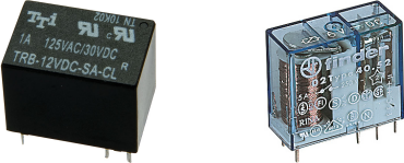
- A single-pole single-throw (SPST) relay has a switch with two terminals — the normally open (NO) terminal is connected to the common (COM) terminal when the relay coil is activated.
- A single-pole double-throw (SPDT) relay has a switch with three terminals — the normally closed (NC) terminal is connected to the common terminal when the relay coil is deactivated.
- A double-pole double-throw (DPDT) relay has two double-throw switches with three terminals each.
A relay’s coil is activated by connecting its two terminals to a power supply, normally between 6V and 24V DC.
If you are lucky, your relay may have its terminals labelled, otherwise you will need to check your relay’s datasheet or do some testing with a multimeter set to its resistance (Ω) or continuity (diode) ranges to determine which terminal is which.

Relays cannot be directly connected to your Arduino/Genuino Uno or Mega for several reasons:
- They generally require a higher voltage and current than the Arduino/Genuino Uno or Mega can supply.
- The counter-electromotive force produced in their coils would damage the Arduino/Genuino Uno or Mega.
A circuit called an H bridge can be used to solve all of these problems.
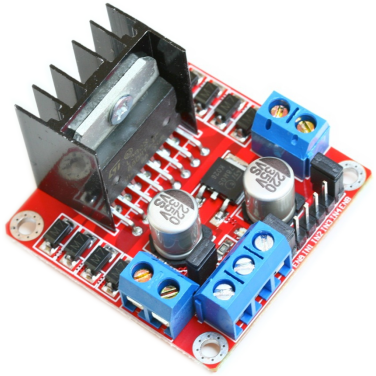
One of the most popular H bridge circuits is based on the L298 integrated circuit. It contains two identical H bridges, allowing you to control up to four relays consuming up to 2A each at a voltage from 7.5V to 46V DC.
While you could build your own L298 H bridge circuit, it is cheaper and easier to buy a ready-built module. The examples below assume the use of such a module running from a 12V DC power supply, along with a relay having a 12V coil.
Relays generate electrical noise, which may cause other components such as your Arduino/Genuino Uno or Mega to behave erratically. To stop this happening, you may need to connect a 0.1µF ceramic capacitor (µF is pronounced ‘micro-Farad’) between each relay’s coil terminals, as shown with dotted wires in the examples below.
Connecting relays
Relays can be connected to your Arduino/Genuino Uno or Mega and L298 H bridge module using any of the inputs and outputs, as shown in these examples:
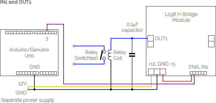
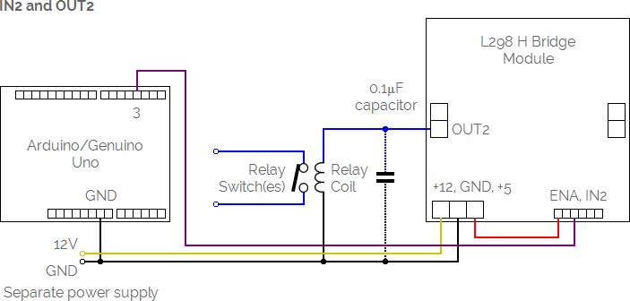
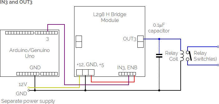
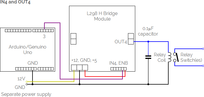
The input (IN1, IN2, IN3 or IN4) from the module can be connected any of the digital pins on your Arduino/Genuino Uno or Mega, labelled 2-13 on the Uno and 2-53 on the Mega.
Once your relay is connected to your Arduino/Genuino Uno via an L298 H bridge module, use the Connect command to give it a name and tell MECControl which pin it is connected to:
Connect Heater Relay To Pin 3
In this example, a Relay named Heater has been connected via the digital pin labelled 3.
You can then refer to the relay by name in later commands, as in this example:
Activate Heater
This will activate the Heater relay. The following command will deactivate it:
Deactivate Heater